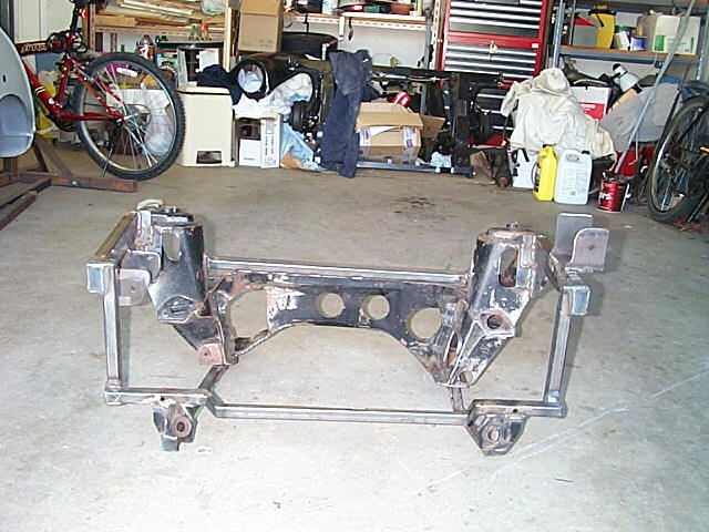
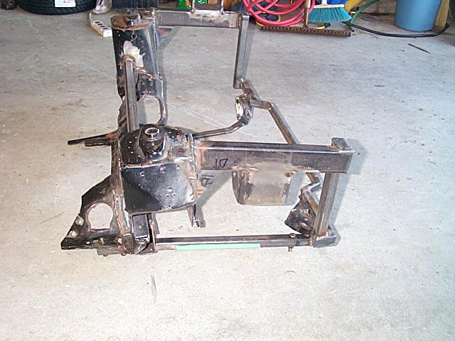
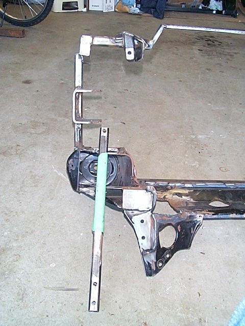
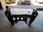
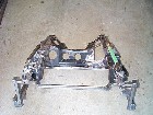
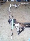
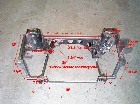
| 1. The frame completed. I will add brackets for the brake lines later,
as well as the torque bar. |
 |
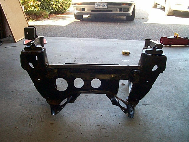
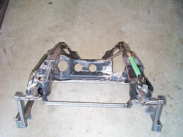
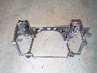
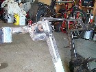
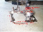
2. ...and the rear of the finished frame. You can see the hole for
the tranny clearance |
 |
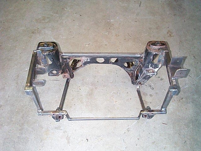
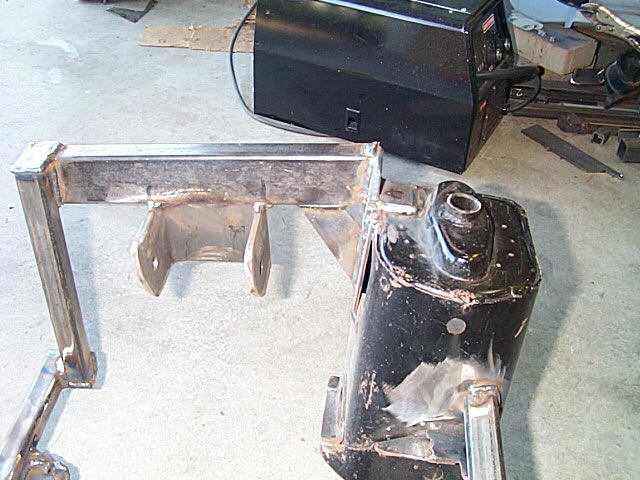
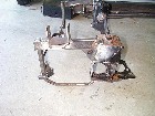
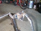
| 3. A top shot of the frame. The lower bar on the right side of this
picture is removable to make it easier to get then engine into the frame. |
 |
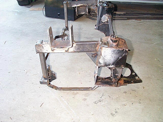
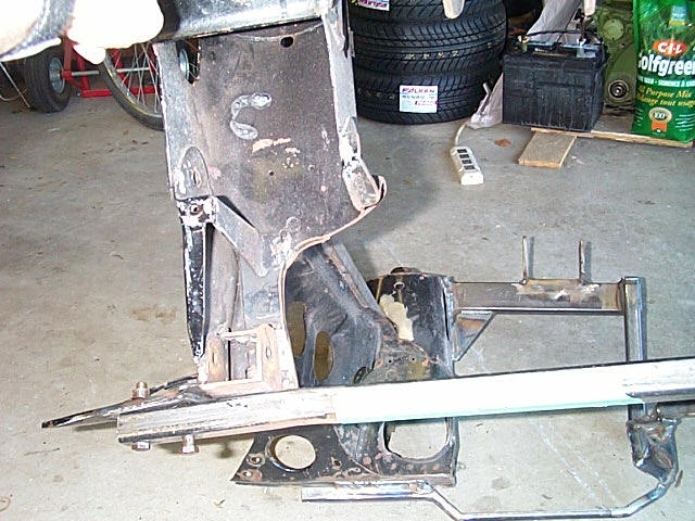
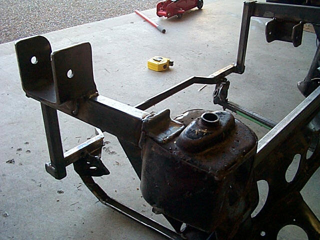
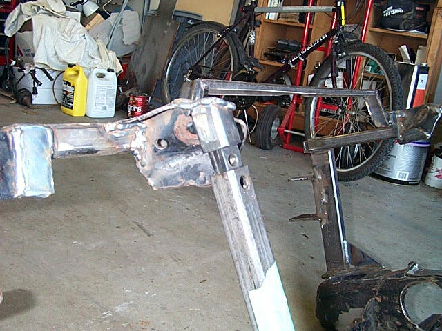
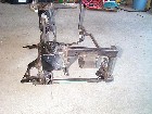
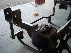
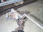
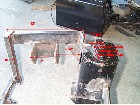
4. A view of the LH side support bar. I have welded on an piece of
flat bar at an angle to help support the bar. You can also see the lower
bar which drops to clear the oil pan. |
 |
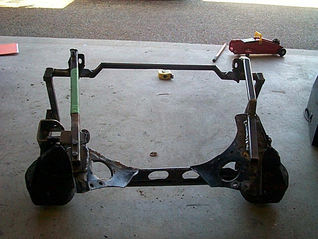
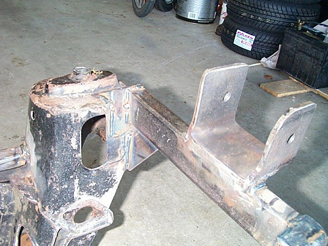
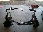
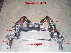
| 5. The RH side support bars. The lower bar with the green tape
on it is the removable one. The support bar sits higher than the top of
the tower and has an additional angle iron bracket welded in for support. |
 |
6. Here is another view of the RH side and lower arm. The lower bar
is held in place by two bolts at the rear and one at the front. The rear
section was plated with 1/8" steel to help support the rear of the bar. |
 |
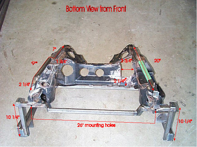
| 7. A bottom view of the frame looking from the front.. |
 |
8. And the bottom view from the rear.. |
 |
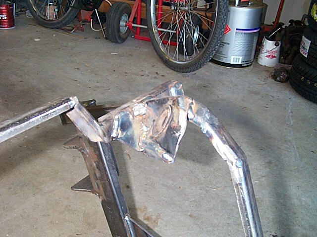
| 9. A close-up of the LH support arm. A piece of 1/8 plate 3 1/2 x 1"
was welded across the opening on the tower to provide some place to weld
the arm to. A 2"X3" 1/8" plate was also welded to the end of each
of the support arms. |
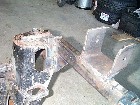 |
10. Here you can see where part of the 2'x3" plate sticks up above
the tower. For added support some angle iron has been welded between the
top of the tower and the plate that sticks up. |
 |
| 11. This is the RH side..same comments as the LH side. The 2X3 plate
sticks up higher on this side so you can see the added angle iron support
better. Also you can see the added support under the arm. |
 |
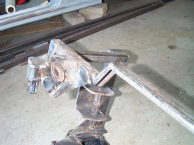
12. This shows the removable lower bar on the RH side and the plate
added to the frame with the holes drilled. The top slides over a plug at
the front of the frame. |
 |
| 13. A close-up of the RH lower bar sliding onto the plug. |
 |
14. Close-up of the LH side, including the mounts for the struts. These
were cut off the original frame and reused. |
 |
| 15. Close-up of the RH side strut mounts. You can see the extra reinforcing
plate that has been welded into place. |
 |
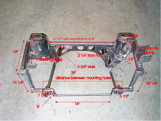
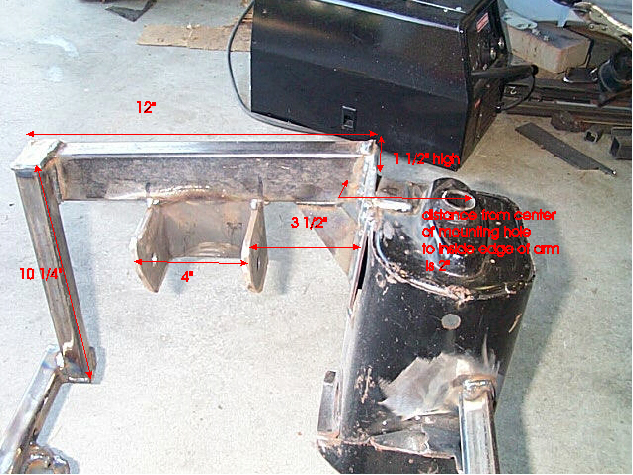
16. Front view with dimensions. These are my finished sizes, I recommend
you use these as guidelines only. check everything against your engine. |
|
| 17. Measurements for the RH side support arm. You can see the lower
arm is removed in this picture.. |
|
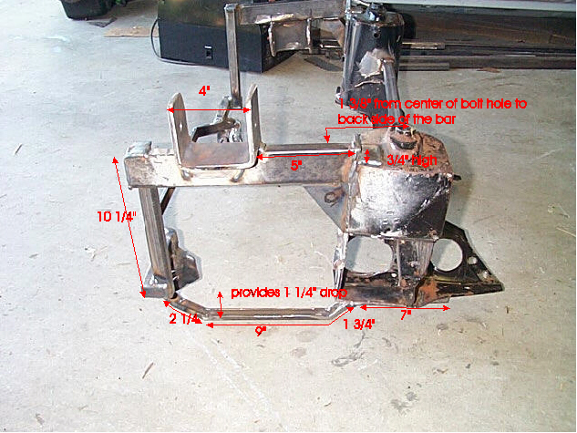
18. And the LH side support arm and lower bracket. |
|
| 19. Rear view with measurements.. |
|
20. NOTE: the front bar of the subframe was modified from the diagrams
above to come out 1" farther in the front to clear the exhaust manifold.
You can see that in the pictures in the buildup area of the website. The
engine was also lowered approx 1/4 inch to ensure clearance for the driveshaft
on the passenger side. Please take this into account if you are using my
diagrams as a guide. |
|
| 21. Make sure you verify the fit with your car and engine, before the
final welding! |
|
22. No guarantees or assurances of suitability for your project are
implied or supported by this website or the information provided. Use this
information at your own risk!. Thanks |
|