| MiniSuki's
Project -Suzuki Install 1
|
| This is the step by
step process of fitting a Suzuki engine to a Clubman as provided by Minisuki.(Chris
B). Have fun taking a look through these pages...Mike
Well here goes, after finishing the 3cyl conversion on
my car I wanted to do another one. Originally I wanted to install the G13B
in the Mini but at the time I could not find a car that was not running,
and could be bought cheap so the 3cyl became the first
|
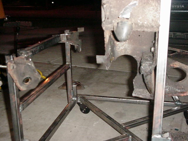
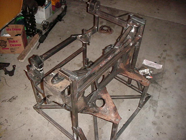
| 1. Starting off to build a jig using the old frame for reference. | 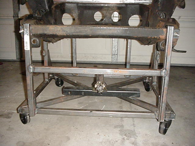 |
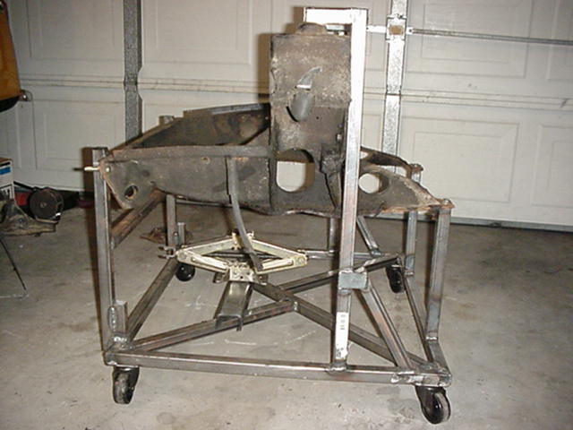
2. Here are some other angles of the jig with the frame installed in
it ,I also
put wheels on it so it could be moved around in the garage if I had to. |
 |
| 3. The next few shots are of various angles of the jig... | 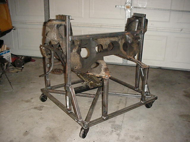 |
4. and the top view... | 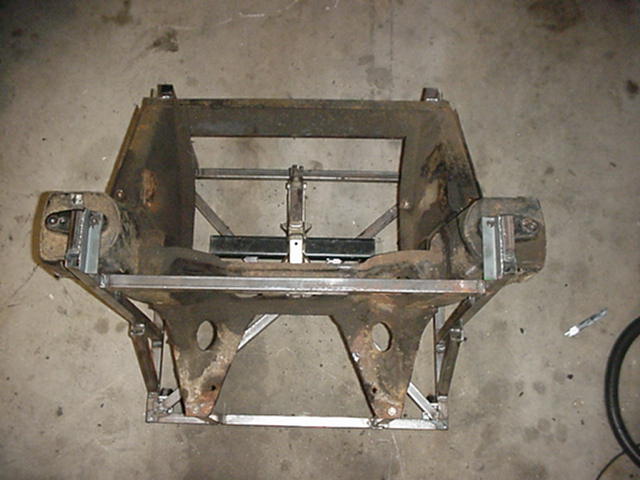 |
| 5. Another side angle view from the rear | 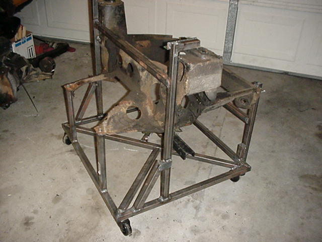 |
6. ...and from the front | 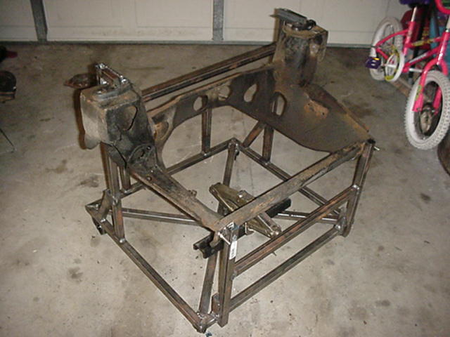 |
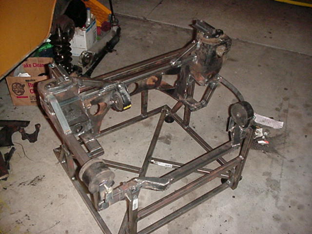
| 7. After fitting the frame was done, then came the serious stuff, actually cutting the frame. Because I had done this before I had some idea of what had to be removed like the sides of the frame where the Minis engine mounts sit, as well as the part of the frame where the axles pass through | 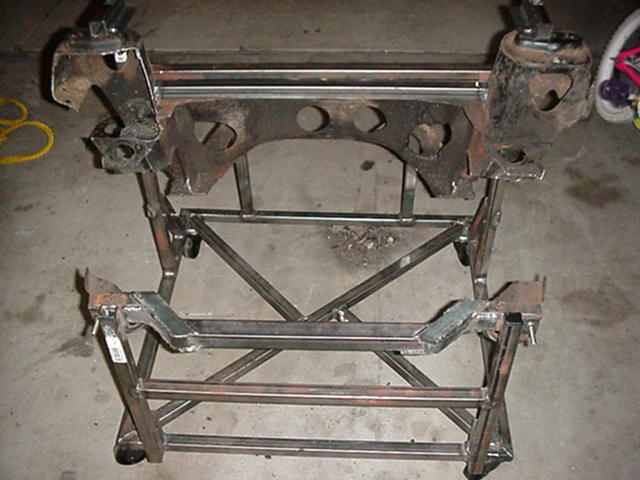 |
8. If you look at the front of the frame, you will notice that it has been extended so that the exhaust manifold and down pipe can pass between engine and frame. The metal that was used for this was 2 inch by 1 inch, and also 1 by 1 box tubing. The front portion is 1 1/2 box tubing | 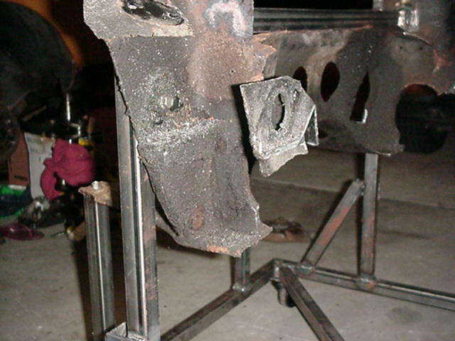 |
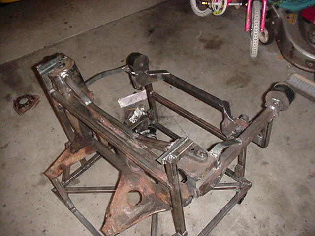
| 9. This is what the other side of the frame looks like, notice how
much of the
original frame has been removed. |
 |
10. This is where it got tricky, trying to see where the engine and gearbox would sit in the frame. Another thing to remember, the engine sits at an angle in the Swift so this had to be done here also. So magnetic angle gauge was purchased to make sure I got this as close as possible. These pics show the fitting of the assy. | 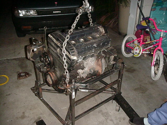 |
| 11. This process was done several times to make sure there was enough
clearance
between engine and frame. |
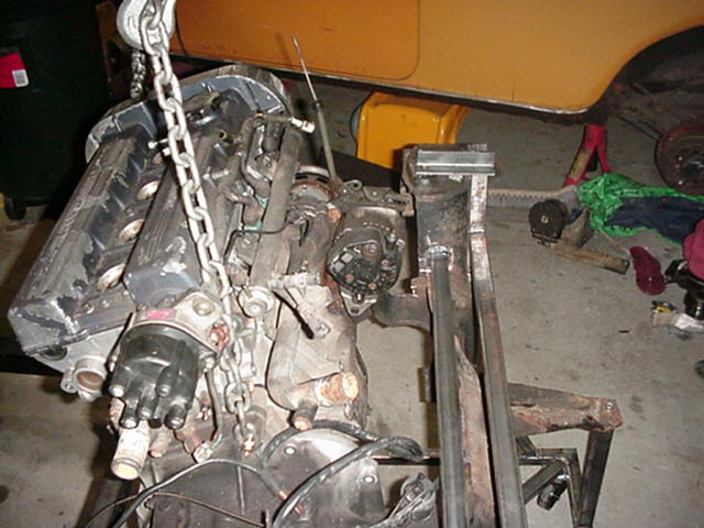 |
12. Here are some more pics of that process. | 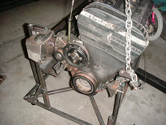 |
| 13. A front view with the engine in place for fitting. | 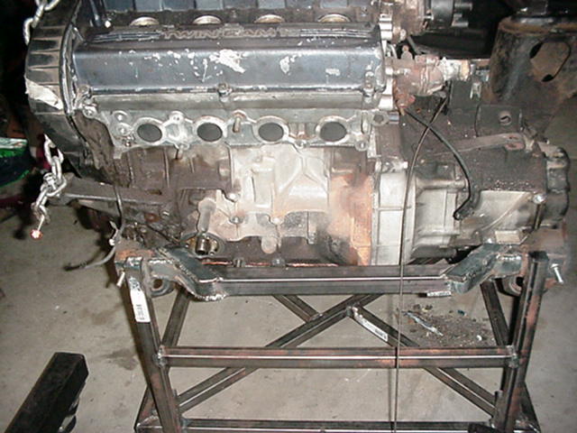 |
14. And a close-up view from the side of the jig... | 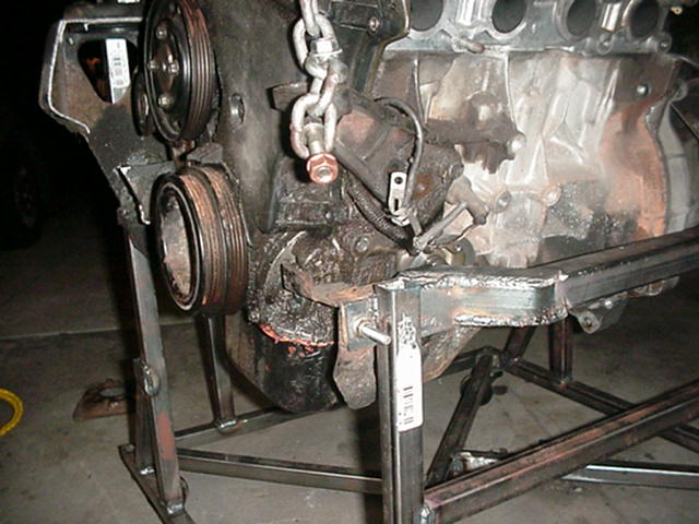 |
| 15. Can't figure what happened to the pics showing the process of the frame being built but here's what I ended up with. I used the stock mounts that the engine came with and as you can see the engine sits where it supposed to be. |
 |
16. Another view of the frame. |
 |
| 17. View from the rear |
 |
18. Other side from the rear |
 |
| See the next page for more info and pictures.... | ||||
|
MiniSukis Project | Page 1 | Page 2 | |